The Sharp Carousel Microwave was working well but the display was becoming unreadable
Try this for a fix.
Make sure the power plug is removed from the wall socket as mains wiring will be exposed.
You need to dismantle the oven a bit so get the medium sized cross head (Philips) screwdriver
and a small one for slotted screws. The control console comes out as one piece and can be worked at on the bench.
The case is held on by 5 screws, one at the bottom right and 4 at the back, remove them.
 Lift the cover up an inch at the rear and slide it back. It should become free but could be held by food residue.
At the top of the control console is a screw holding it to the case, remove it and the console should be
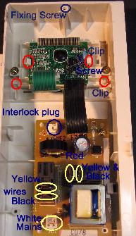
free to slide up and out. There will be wires attached to it though. These have to be unplugged. The spade Lugs
have a little clip built into them that has to be released with a small screwdriver or something before
they can be pulled off. See the picture for wire colors and locations. Once off, the console is free.
The electronics are at the top, pull on the green ribbon cable and it should come out of the white holder
on the pcb. There are 2 clips on the side of the pcb, they may have goo on them, remove it and prize the
clip on the right hand side out so that the pcb is released. Slide it out from the other one.
Remove the 2 screws holding the display cradle and prize the clips until the cradle can be released.
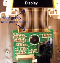
Both the ribbon cable ends can now be seen. The picture shows the display further disassembled
and spread out but this is not needed for a fix. With a hot air blower gently heat the indicated ends of
the ribbon cable - not too hot or it will come free, unglued, When it is warm to the touch (about 5 seconds)
push the contact area on the cable hard down onto the pcb or display glass. A roller wheel or screw driver
blade dragged over the contact area works.
 If you are experienced, the unit can be powered up while out of the microwave. There needs to be a
jumper connecting the 2 pins of the connector near SH-A on the main board. This is in place of the interlock switches.
The neutral mains wire has to be connected to CN-A, the pins are common, and the phase or active
wire to the spade lug at RY-1 where the black wire came from.
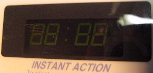
With the power on you should see this display showing all segments of the display are working.

If you find this of use please send me an email at
or sign my Guest Book on the main page.
2nd June 2009..
| | ||
| |
|